- Home
- About Us
- Machines
- Cups & Containers
- Support
- Contact Us
- Customer Portal
Service Bulletin: SB 106.1
Subject: Bottom Finish Station Adjustments
Recommendations:
The new Hi-speed PMC machines have a first dwell point which is shorter than the first dwell point used on earlier machines.
This service bulletin pertains to the bottom finish cams used in the following machine series:
PMC-1000 – 7090, 7100, 7200, 7230
PMC-1250 – 9020, 9030
GX-1000 – 8660
The adjusting procedure described below should be followed when bottom finish adjustments are performed on the machines in the series listed.
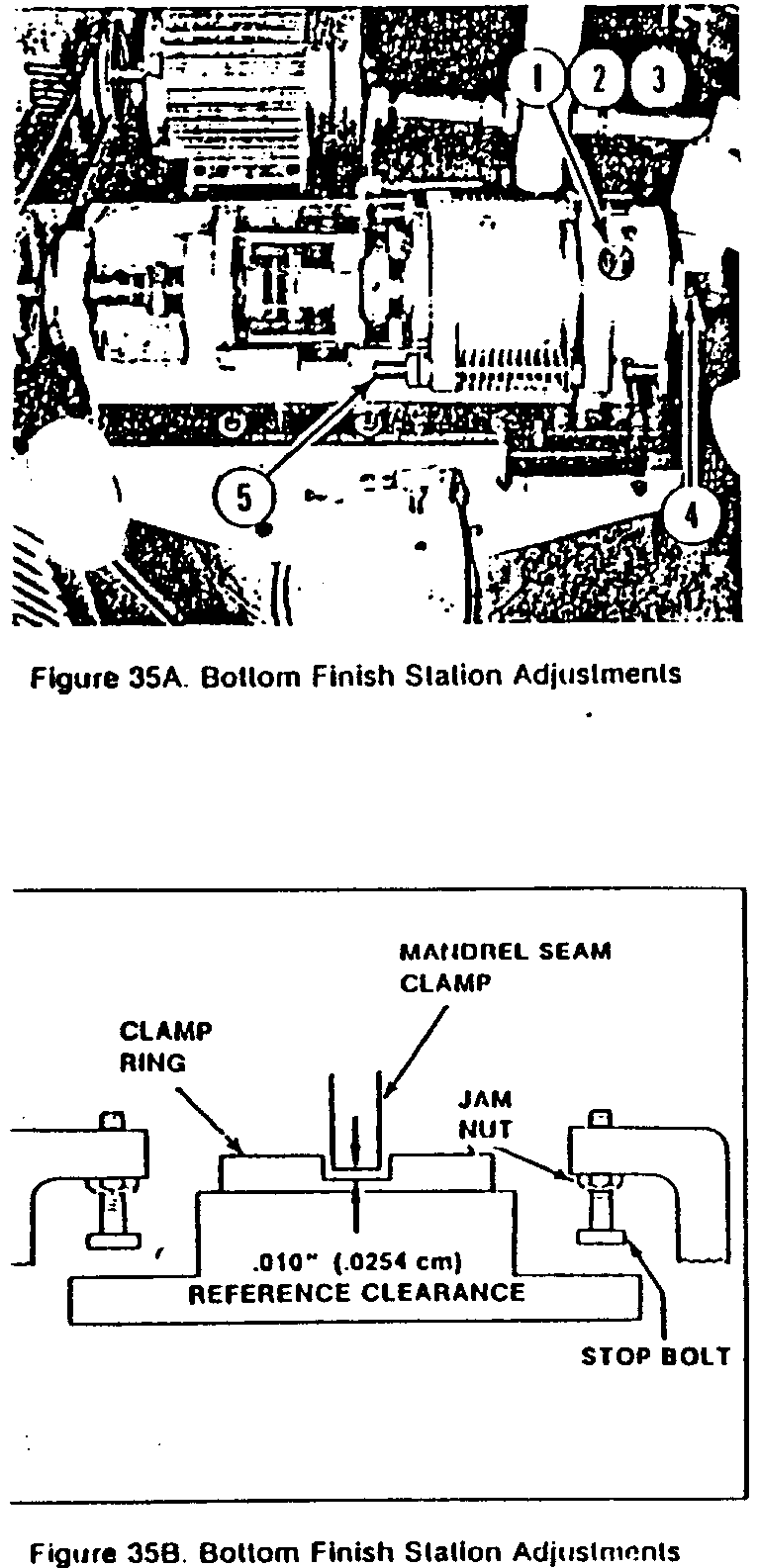
To adjust the clearance between the tool head slot and the mandrel seam clamp, manually operate machine until station has reached the first dwell point on its inward travel. The first dwell point on the new Hi-Speed machines is located at a position .750 inches ( l9mm forward of the station’s fully retracted position. This position must be set within +.005 (.13mm) in order to avoid unnecessary station noise and stop bolt wear.
Loosen the jam nuts and slack off the two stopbolts located in the stationary stopper brackets (see Figure 35B). Evenly adjust the two spring equipped tie rods (5) until the reference clearance between the vertical tool head slot and the mandrel seam clamp is approximately .010″ (0.25mm). Then take up slack betwen the two stop-bolts and the tool head and lock jam nuts.
Run machine to obtain cup sample on mandrel for measurement of bottom depth. If bottom depth does not conform to cup specifications drawing, repeat adjustment at first dwell point and adjust in or out as required.
