- Home
- About Us
- Machines
- Cups & Containers
- Support
- Contact Us
- Customer Portal
Service Bulletin: INST 90.3
Subject: Replacing Followers Without Removing Follower Plate
Recommendations:
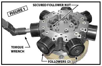 Follower Removal & Replacement
The following Bluing procedure will determine that the cam is on center before the clearance can be checked:
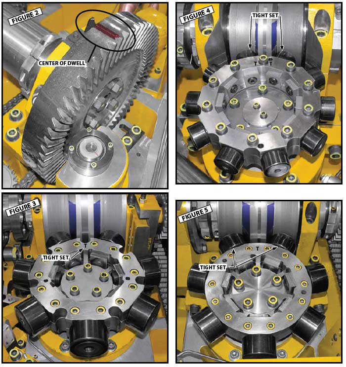
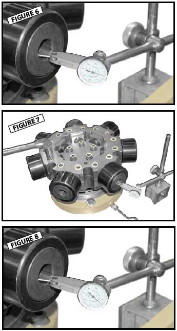 With all follower installed and centered to the cam, the clearance must now be checked, and reset if necessary. The proper clearance is 0.0001″ – 0.0002″ on the tightest set (when tightest set measurement is achieved, you should feel contact of the roller to the cam); and 0.0013″ on the loose set. Proceed as follows:
NOTE: The letter “T” is stamped on the follower plate to indicate the tightest set and the letter “L” to indicate the loose set. The letters are stamped on the follower plate with the original set of followers at the factory but may change when new followers are installed. It may be necessary to re-stamp these if the new followers checked out differently.
NOTE: This procedure may have to be repeated until proper set up is achieved.
 After all followers have been replaced and the proper clearance set, use the following Bluing procedure to check for hard-lining and flatness of the followers tracking on the cam.
Hard-lining is a heavy mark that is not even across the entire follower.
If further instructions are needed, please contact Paper Machinery Corporation’s Service Department.
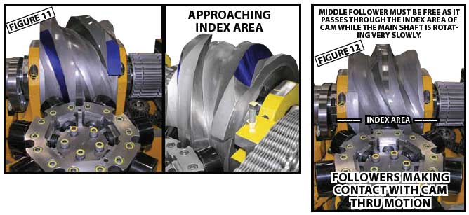
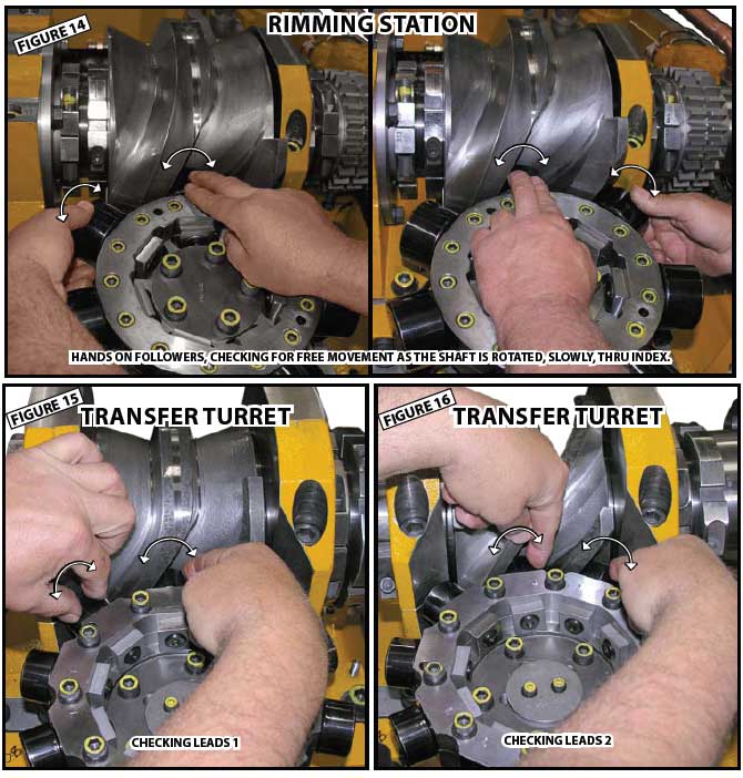
When the main shaft is rotated (slowly) thru index, under no circumstances should all three followers lock up on the cam. There must be one follower that turns freely. This ensures that the followers are controlled properly as they move thru the index area. Failure to achieve this requirement will result in Cam and Follower damage!
It is strongly recommended to have 2 personnel assisting along during this procedure. One (1) assistant is needed to rotate the machine, by hand. One (1) assistant is needed to insure that proper communication is made between the person rotating the machine and the person checking the followers.
|
WARNING! Because this procedure can only be done while the main shaft is in motion (rotated), extreme care must be used. It is important to fully understand & follow all the safety and warning labels before starting this procedure. |
|
WARNING! Permanent cam damage will result if too much material is removed! Polish/stone only enough material from the tips to free the followers. |
|
WARNING! Due to the high risk for serious injury of this procedure, it is strongly recommended that all spring loaded stations be unloaded prior to this procedure (for Blank Fed machines). Spring loaded stations: Bottom Finish, Bottom Disc Heat, Bottom Heat, Shuttle Drive Stations |
 If follower lock up has occurred during the “Tight Set of Followers” procedure, polishing/stoning of the cam lead tips will be required.
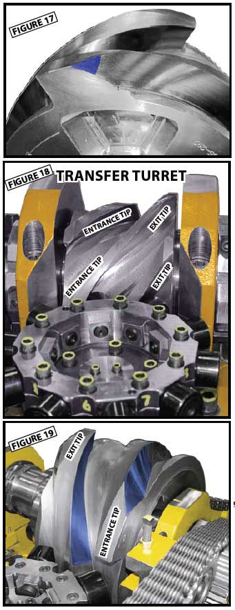
Refer to Figure 17 for the proper location to be polished/stoned.
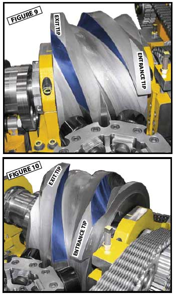
It is important to understand which tip will need to be polished/stoned if it becomes necessary to do so. Figure 18.
Entrance:
As the shaft is rotated, and the follower on the entrance tip makes contact with the cam, the middle follower should turn freely. See Figure 19. If the middle follower does not turn freely, the entrance tip will need to be polished/ stoned.
Exit:
As the shaft is rotated, and the follower on the exit tip makes contact with the cam, the middle follower should turn freely. If the middle follower does not turn freely, the exit tip will need to be polished/stoned.
CONTACT: Parts orders and customer communication can be made using telephone, FAX, or e-mail. Contact can still be made using the main telephone switchboard at 414-354-8050 or FAX number 414-354-8614. Sending a FAX directly to the Service Department, at 414-354-1710, will convey a faster response. If using e-mail and no response is made within 3 working days, please contact via phone or FAX.
Parts orders can be directed to Holly Warner or Vicky Alcaraz using telephone, FAX, or e-mail. Please make sure to carbon copy (CC) both Holly Warner and Vicky Alcaraz in all e-mails containing parts orders. Service issues can be directed to Steve Evans or Mike Ferguson and electrical issues to Larry Spencer.