Service Bulletin: INST 98.1
Subject: Replacing the Folding Wing Puck Assembly
Recommendations:
Dis-assembly Procedure
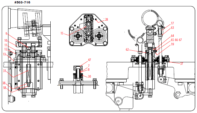
Refer to Drawing #503-716 and proceed as follows.
NOTE: This procedure assumes the Folding Wing Housing has already been removed from the machine.
If the Folding Wing Housing was removed with the Folding Wings attached, remove and store (Folding Wings) until needed for re-installation.
- Clean Folding Wing Housing thoroughly, removing Grease, Dirt and Poly build-up
- Remove (2) Rod Ends [#17 ] and full Hex Nuts [#63] from the Push Rod: Pull the Rods down-and-out of the Puck Assemblies
-
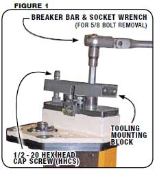
- Use a 1/2″ Allen Socket & Breaker Bar to remove the (2) 5/8 – 18 × 3 Socket Head Bolts [#47 ]
- Remove Tooling Mounting Block [#10], Tube Spacer [#7 ] and Stand Off [#8]. See Figure 1.
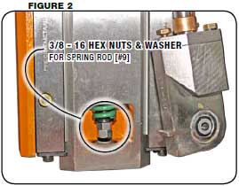
- Remove (2) 3/8 – 24 Full Hex Nuts [#58 ] Full Hex Nuts located at the end of the Spring Adjustment Rod [#9 ]
CAUTION! The Rod is under pressure and needs to be handled with care while removing the Spring.
- Remove the Spring [#31] and Washer [#38 ]. See Figure 2.
-
- Un-screw (2) 10 – 32 Socket Head Screws [#65 ]
- Remove the Anti-Rotation Plate [#19 ] with the Dowel Pin [#64 ] attached.
-
- Un-screw the (6) Socket Head Screws [#62 ] from the Shaft Seal Cap [#11].
- Remove the Shaft Seal Cap with the Spring Rod [#9 ] attached.
-
- Unscrew the (6) Socket Head Screws [#28 ] that holds the Upper Slide Housing [#12 ] and the Slide Plate [#13] together.
- Separate the 2 Plates
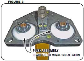
- Remove the Puck Assemblies. See Figure 3.
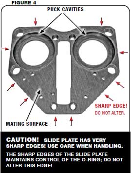
- Examine all of the Puck’s disassembled components for wear. Look for wear in the Puck Cavities. It may be necessary to grind the Upper Slide Housing or the Slide Plate (or both) to restore the mating surfaces.
NOTE: If the Puck Cavities are severely worn and cannot be restored by stoning, the Slide Plate must be replaced
Assembly Procedure
Refer to drawing #503-716 and all Figures. Proceed as follows.
- Prepare all surfaces for reassembly
Replace all O-Rings and Seals on the Assembly.
Stone all mating surfaces on all parts that is to be assembled and app ly a thin coat of light lubricating oil, on all mating surfaces.
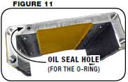
- Install (1) O-ring [#30] in counter bored hole in slide housing [#14]. See Figure 11.
- Use (4) 3/8 – 24 x 1 SHCS [#53] to mount the slide plate [#13] to the slide housing [#14]. Apply locking compound to screws and torque them to 35 ft/lb.
- Next apply thin coat of light lubricating oil to the puck cavities in the slide plate and insert the puck assemblies. See Figure 3.
- Next install the upper slide housing [#12] over the puck assemblies and onto the slide plate.
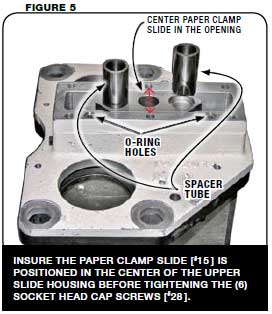
NOTE: Insert the two taper dowel pins that were removed from the housing. This will realign the upper slide housing to the slide plate. If no tapered pins were removed make sure that the upper slide housing is centered to the paper clamp slide before tightening the (6) SHCS [#28]. See Figure 5.
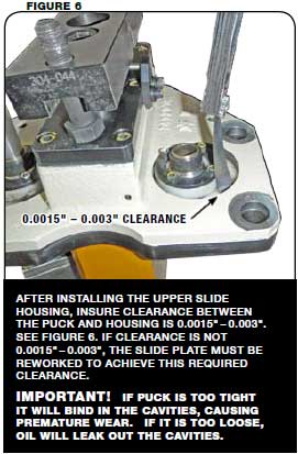
- After installing upper slide housing check puck clearance. See Figure 6.
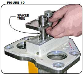
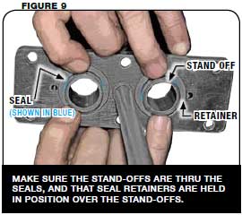
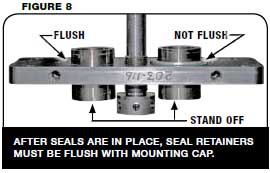
- Next install new seals and retainers into shaft seal cap [#11] with spacer tube [#7] and stand off [#8] and install cap according to Figures 7 – 10.
NOTE: Remember to insert (2) O-Rings in counter bored holes on the mating surface for the upper slide housing. See Figure 5.
- Lock cap in place with (6) 1/4 – 20 x 1/2 SHCS with locking compound.
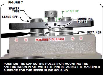
- Next adjust the spring rod (up/down) to obtain 1/4″ set up gap between the top of the shaft seal cap and bottom of the adjusting rod. See Figure 7 and replace the anti-rotation plate with pin. Apply locking compound to the (2) 10 – 32 x 3/4 SHCS and tighten screws.
- Next insert the 1/2 – 20 Hex Head bolt that was removed during disassembly and mount tooling block [#10] in place securing it with (2) 5/8 – 18 x 3 SHCS. Torque them to 180 ft/lb.
- Install rod spring [#31], (1) flat washer [#38] and (2) full hex nut [#58]. Make the nuts flush with the end of the rod. See Figure 2.
- Complete the assembly by installing the (2) push rods and all remaining parts.
IMPORTANT!
If rework was done to the Upper Slide Plate, Slide Plate or Puck Cavities, the wings must be refitted and new spacer ground to set lower clamp pressure.
CONTACT: Parts orders and customer communication can be made using telephone, FAX, or e-mail. Contact can still be made using the main telephone switchboard at 414-354-8050 or FAX number 414-354-8614. Sending a FAX directly to the Service Department, at 414-354-1710, will convey a faster response. If using e-mail and no response is made within 3 working days, please contact via phone or FAX.
Parts orders can be directed to Holly Warner or Vicky Alcaraz using telephone, FAX, or e-mail. Please make sure to carbon copy (CC) both Holly Warner and Vicky Alcaraz in all e-mails containing parts orders. Service issues can be directed to Steve Evans or Mike Ferguson and electrical issues to Larry Spencer.